Object Process Methodology was approved as a standard ISO/PAS 19450. In representing systems, it’s worth spending some time getting better with its constructs, as well as the support tool (Opcat).
Understanding happens top-down. I’m now getting to a level where I need to appreciate the tool more, and use it effectively. This example, published in 2007, is helpful.
– begin excerpt –
3.3. Modeling the Distiller with OPM
… definition of the system boundaries: defining its main process, which is the major function of the system being modeled—in our case Purifying. Around this process the involved objects are depicted: affected object (Water in our case), inputs and outputs, main agents (OPM actors) if they exist, and possible environmental (external) objects and processes involved. Figure 4 depicts the System Diagram (SD, the root of the OPD hierarchy tree) of the distiller system. This top-level diagram emphasizes Purifying as the system’s function, its major goal. This is typical of the top-level OPD of any OPM model: The sole process it displays is the system’s function.
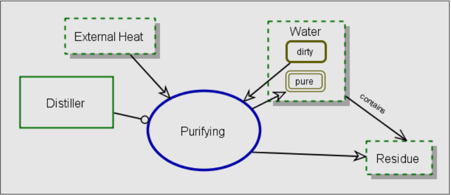
Figure 4: The System Diagram of the Distiller System in OPM
Next, hierarchical refinement of the system processes and objects takes place concurrently, using the refinement mechanisms of in-zooming for processes and unfolding for objects. Figure 5 shows the Purifying process in-zoomed. A detailed sequence of subprocesses included in the purifying process, shown inside the Purifying ellipse, includes Heating, Boiling, Condensing, and Draining. The Y-axis within an in-zoomed process is its timeline—it specifies the sequencing of the operations: Heating, placed at the top is the first operation. It is followed by Boiling, Condensing, and finally Draining. The diagram also specifies the structure of the distiller by showing its parts: Heat Exchanger, Boiler, and Valve. Each subprocess uses a different subset of parts of the Distiller and changes the state of Water from dirty to hot, boiling, and finally pure.
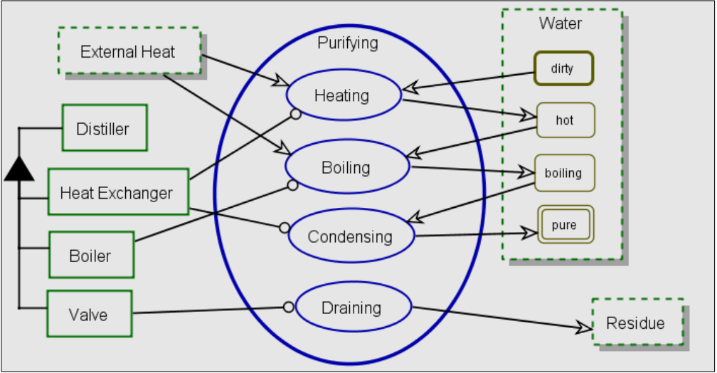
Figure 5: In-zoomed Purifying process in OPM
The 3D shading effect of the entities in the OPDs symbolize that they are physical. The dashed contour of the Water and External Heat objects denotes that they are environmental, i.e. not part of the system. This distinction clearly delineates the border between the modeled system and the external entities, which are part of the system’s environment. OPM supports textual representation of the model additionally to the graphical description. The OPL text for the OPD in Figure 5 is listed in Figure 6.
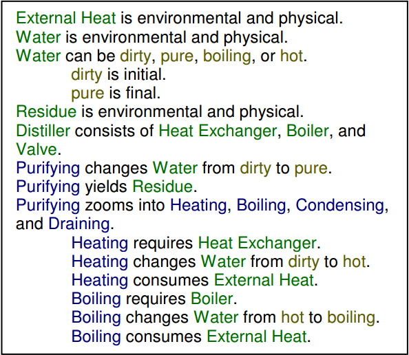
Figure 6: The OPL paragraph that describes textually the OPD in Figure 5
– end excerpt –
In the recent thinking about yin-yang, there’s a correspondence between water-fire in this example that is worth thinking about.
Source: Grobshtein, Yariv, Valeriya Perelman, Eliyahu Safra, and Dov Dori. 2007. “Systems Modeling Languages: OPM versus SysML.” In 2007 International Conference on Systems Engineering and Modeling , 102–109. IEEE. https://doi.org/10.1109/ICSEM.2007.373339. Cached at
